When MOTOROLA first brought out the incredibly light-weight, high efficiency and cheap Piezo tweeters, the first thing that
struck most people was that they sounded a bit harsh. Well yeah, they did. That was simply because they handle the top end of
the audio so well, we were hearing things we'd never heard in our sounds before,.. like hiss and tiny ticks that really pissed
off our pet dogs! (and I dont mean the ticks as parasites either!)
The most common mineral in the planet is QUARTZ and it was MOTOROLA who made a disc of this stuff vibrate at high audio with
amazing precision to give us the PIEZO HORN TWEETER. I still get sound engineers who tell me the traditional compression
drivers sound better but to be honest, there is one thing that a lot of these guys don't seem to understand, compression
drivers still roll off the top end. If their sound system sounds harsh with piezo horns, it's
producing a harsh sound which
will still be causing other forms of distortion, just because it's not that obvious in the compression drivers as sound output,
doesn't mean it's not cookiing the coils! That is the main reason compression drivers burn out,.. and also why there is a good
market for spare diaphrams at ludicrous prices!
So, the question that I get asked a lot is this,..
"Can I get a Piezo horn to sound a bit less harsh, more like a normal coil comression driver?"
Well yes is the simple answer but it will also bring into question the way you have been using your particular system too. By
that I mean you must realise that if there is a lot of hard very high end stuff with a basic piezo tweeter, find out why because
that shouldn't be there in the first place should it?
Understanding how a piezo device works is really the job of the people who make them,.....
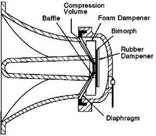
.. go take a look at thier site if you want the technical low-down but in basic terms, the image below is a cross-section
through a typical standard piezo horn.
The 'Bimorph' is the business bit of the device, a very precise disc of piezo that is connected in its centre to the diaphram,
which is usually the thing that falls off when one of these fails!. Ok that's the 'standard' one and rated as handling "75 watts"
but that is a bit of a mis-direction,..these things look to an amplifier output, like a pretty high resistor in series with a
slightly lossy capacitor, hence they really don't load the amp at all! A piezo device doesn't really start to do much until it
gets frequencies of 3KHz and even at the very top end of its range it's still well over 50 Ohms and as anyone will tell you,
they don't need a crossover!
WRONG! YES THEY DAMN WELL DO!
OK, not quite in the same way as a compression driver, but more in the manner of limiting the voltage that arrives at the terminals!
If you go to the Piezo Source website, (that's the logo link above here) smack in the middle of that page is a section that says,
"Learn about Piezo technology" and there is a whole lot about how these amazing horns work and several wiring diagrams for
basic connections. Any of those will work but as they rightly point out, a lot of amplifiers in use these days will run way out
of the human hearing range to where only 'Bat-Man' would get the benefits!
Also, a basic piezo device will fry if it gets more than the 75 watts
(75 watts into 8 Ohms = 24.5 vrms)
and as I haven't seen
any PA amps anywhere near as low as that since the seventies, you have to get creative in order to keep em on the same planet
as the rest of yer kit! Given that they are so much more efficient anyway, it's not that hard and being able to wind the level
back off is very handy, not only to preserve the things but to get a sweeter sound too.
What follows are a couple of diagrams to give some variable level control over your horns, thus winding off some of the hard edge
to the sound. What so many people fail to realise is that these tiny devices put out a heck of a lot of sound level for very
little input, hence if you drive them at the edge or the limits of voltage, they will distort very fast and obviously! (Then blow up)
What a lot of engineers never take into consideration is that, particularly in rock music, there is a pretty high level of
bass end and often that has some pretty hefty peaks in it. The highest value of say a 300 watt bass note will be 600 watts,..
for a piezo device, that is going to look like a very sustained voltage compared to what it 'works with' and a bit like having
a bass speaker given a burst of DC several times its working max level!
(I really don't want you to try that out, you may well
end up with your cone/coil assembly buried in the bedroom wall!!)
So, to initially prevent such peaks of low frequency trashing your peizo horns, as the Piezo Source guys suggest, pop a capacitor
in series and you will be amazed at how much of a difference just that and the 50 Ohm resistor makes in a fixed system!
In these variable circuits, I include a capacitor as well and I've had people swear blind I'm using really expensive compression
drivers,.. I tend to keep the facts quiet because they tend to get a bit upset about that for some reason!
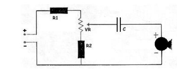
Right. First up, simple single horn. For this you need
1 x 15 Ohm 5 watt resistor,
1 x 33 Ohm 5 watt resistor,
1 x 100 Ohm 2 watt wirewound potentiometer (not a little carbon track, it will get smokey in there!),
and
1 x capacitor to suit the low-end point of the horns you are using.(See the Piezo Source website for details!)
Ah, and the horn of course!
I know that you will see other diagrams state that the resistors only need to be 2 watts but I always over-rate
my circuits, which means they tend not to fail on me! Be a tight-wad if yah want but don't say I didn't warn yah!
You need to find somewhere to mount the Pot on your cabinet where you can get to it but not smash it off in transit! That's not always
as easy as it sounds because the body of the thing is a bit fat isn't it!
The wiring shown here is pretty straightforward and if it all looks very weird and baffling, get a mate who it understands it
to do it for you! If you don't understand this sort of schematic, you shouldn't be messing with this shit!
R1 is 15 Ohms, R2 is 33 ohms, the VR is the Pot and C is the cap. The +/- terminals connect to your loudspeaker socket. I say
this because if you loudspeakers have anything other than solder terminals, things can and do tend to go wrong! This circuit
gives a fair amount of adjustment of the level but bear in mind that it's not exactly working in the same way as a volume pot
because the piezo is still prety sensitive at lower voltages!
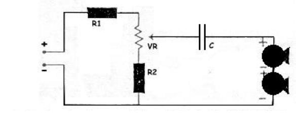
For two horns in series, on an amp up to 300 watts, the values are much the same but the cap might change,
I say this because adding capacitance in series reduces the overall value and tweaks to the cut-off point may be advised with
a little experimentation. You have to remember that the piezo looks like a capacitor,.. hence the variation!
The POWERLINE range of horns are rated as handling up to 400 watts (or the equivalent RMS volts) and they do this by having a
light bulb in series with the 'bimorph' which tends to act as a simple limiter, along with a PTC heat sensor. Again, see the
Piezo Source website for this in more detail. Basically the same components can be used to wire these higher power horns too,..
but if you want to go for more than two, the Potentiometer is gonna have to be a fat
5 watt device or it will burn out very
fast!
How these variable circuits work is that as the frequency increases, so the effective resistance of the horn drops. The potential
divider network created by R1+VR+R2 gives a fixed resistance at the wiper to the postive line, hence as the frequency rises,
the horn gets progressively less level,.. the result is that the harsher really high frequencies are now at a much lower level
compared the overall sound and hey presto,.. you have pretty much the same response as those great hefty coil drivers at a
fraction of the price! It also serves to protect the piezo devices from too high a voltage.
Simon has pointed out that the cost of the potentiometer can actually be more than the tweeter itself. Um,.. yeah
it can in some places so if you want to cut down the price and go for a fixed resistor, I don't suggest you rely on
just a single resistor in-line as suggested by most websites. What you need is to have a decent voltage divider so
you don't fry the biomorph. Easy, just leave out the variable and connect the capacitor to the junction of the two
resistors, it works in the same way but you might want to play with the top resistor R1 to get the level to sound
right for your main speakers though.
Simple rule,.. just cos it's not expensive doesn't mean it's not worth getting!
Some examples of these Piezo horns are shown here.
KSN-1005 standard round horn.
KSN-1141 flared horn 2"x6"
KSN-1165 the high power (400 watt) 'bullet tweeter'.
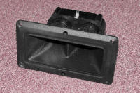
KSN-1177A wide dispersion dual horn.
KSN-1188 'POWERLINE' 400 watt driver
KSN-1151 horn flare for 'POWERLINE' drivers.